
A Magnetic Loop Antenna for Shortwave Listening (SWL)
Now that we’re on the downward slope of sunspot cycle 23 (2004) you may have noticed that some of your favorite broadcast stations don’t come in as strong as they did a few years ago. This is especially apparent on weaker DX stations. The whip on your shortwave receiver used to be sufficient to pull in some good DX, but now you find yourself looking for something better.
Maybe you have been thinking, or even have already tried, putting up a wire antenna. This may be a great solution if you live in a reasonably quiet area, noise wise, and your shortwave receiver doesn’t easily overload in the presence of strong signals. Perhaps you live in an apartment or are situated where installing a wire antenna is simply not feasible. Or maybe you’re looking for something that offers a bit more mobility so you can take it into different rooms of your house. Consider the small single turn magnetic loop antenna if any of the above situations apply to you.
Small Single Turn Magnetic Loop
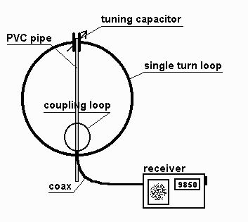
The small single turn magnetic loop (SSTML) antenna consists of a single winding inductor, about 3 feet (1 meter) in diameter, and a tuning capacitor. A second loop, which is one fifth of the diameter of the large loop, is connected to the feedline and this small loop is positioned in the large loop on the opposite side of the tuning capacitor.
The SSTML has some very interesting properties:
| a) | It
has a small footprint. The loop I describe here looks like
a circle in the |
| b) | It
is a rather quiet antenna. It doesn’t pick up as much
man-made noise |
| c) | This antenna is somewhat directional, which can benefit
you in two ways. You |
| d) | Since this antenna is really a tuned circuit, it also acts as a preselector. It only receives well in a narrow bandwidth of a few hundred kilohertz (kHz). The antenna requires retuning if you change the frequency on the radio by a hundred to two hundred kHz. This may sound like a disadvantage, but if you have ever tried a long wire antenna on a rather sensitive receiver, you probably have noticed that your receiver may get overloaded, resulting in hearing multiple stations at once or hearing broadcast stations on frequencies where there really aren’t any. This may make it impossible for you to pull in that DX station you’re really interested in or even make listening to a strong broadcast station rather unpleasant. This antenna will help prevent overloading your receiver. |
When you search the World Wide Web for magnetic loops, you usually run into magnetic loops meant for transmission in the upper ham bands, perhaps 14 MHz and above. To be able to transmit on these loops you’ll have to follow stringent design rules in order to maximize the efficiency of the loop. If you’re interested in a receive-only loop, then the design rules become very relaxed. There’s no need for large diameter tubing and neither for a low loss capacitor to successfully build a loop antenna. On this page I will present a description of my SWL loop.
Main Loop
I built the main loop of my SSTML from quarter-inch diameter soft copper tubing. This type of tubing is used to hook up an ice maker in a fridge to a water line. It’s rather flexible and keeps its shape nicely after being formed into a circle. This kind of tubing comes in lengths of 10 feet in a bag, and you can find it at most hardware or appliance stores for about $6. In fact all parts, except the tuning capacitor can be obtained from the hardware store. You can also use large diameter copper ground wire for the main loop. #6 will do just fine. However, this wire is rather heavy and not very flexible. I’ll assume we use small diameter copper tubing.
Take the coiled tubing out of the bag and unroll it on a flat surface. A hardwood floor would be ideal. When you unroll the tube, try not to unroll it into a straight line. Instead, try to make a large circle while you unroll it. You’ll see that this is rather easy to do. This will ensure that you get a nice circular shape that requires very little additional bending. This is more about aesthetics than performance, though.
To support the loop antenna, use a five foot schedule 40 (white) PVC pipe, with a three-quarter inch diameter. You can tie the loop on the pipe with some wire ties, but this will not be very sturdy. It is better to have the loop go through the PVC pipe. The top of the main loop where the ends come together can be mounted on piece of a bamboo skewer (purchased at the grocery store) that goes though the pipe. The bottom part of the loop goes all the way though the PVC pipe.
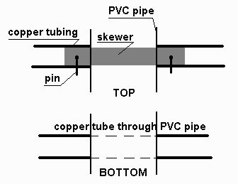
First make sure that the piece of skewer fits snuggly in the copper pipe. Then drill a hole of the same diameter as the skewer near the top of the PVC pipe. Put the skewer in the hole so that about three quarter of an inch sticks out on both sides. Then lay the main loop on the PVC pipe so you can measure where the bottom hole goes. This hole should be the same diameter as the copper tube, and make sure you drill it in the same direction as the skewer. Now move the main loop through the bottom hole until the ends meet near the skewer at the top. Use the same motion as if you would put a key on a key ring. This will ensure that the loop maintains its shape. Then slide the ends of the main loop onto the skewer until the tube is flush against the PVC pipe on each side. Drill a small hole through the tube and the skewer. Next, form a pin from a small piece of solid #14 house wire, and slide it in the hole. Then bend the ends down on each side to prevent the pin from falling out. Do the same on the other side. Now the main loop is securely fastened to the PVC pipe and can still be taken apart if necessary.
Tuning Capacitor
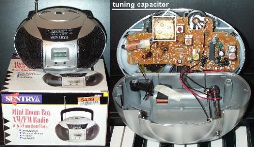
The tuning capacitor I used comes from an old alarm clock that had an AM/FM radio built in. You can find these at yard sales for a buck or two. Another excellent source are those five-dollar AM/FM mini boom boxes. I bought several of these radios at various chain stores and they all have a suitable tuning capacitor. The only thing you need to pay attention to is that the radio is indeed an AM/FM radio and not just an FM radio. These small radios are also a good source for parts for the homebrewer. You get a lot of parts for just $5. The radio below is an example of such a mini boom box. The picture on the right shows you what the tuning capacitor looks like.
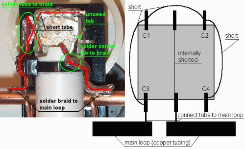
The tuning capacitors found in these radios consist of 4 separate variable capacitors (C1 through C4) and each of these capacitors has a trimmer parallel to it. There’s also a convenient tuning wheel attached to the tuning capacitor. You’ll need that also.
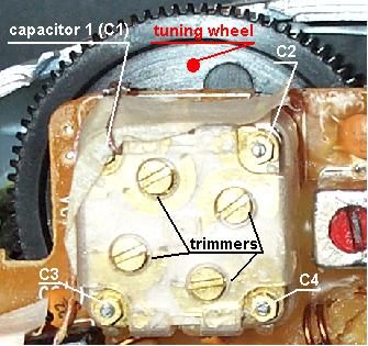
The tuning capacitor can easily be taken off the printed circuit board (PCB) by first removing the tuning knob and the two tiny screws that hold the capacitor to the PCB. Then you can desolder each of the six tabs and the capacitor is detached from the board.
Each of the tabs in the corner is attached to a separate capacitor, as marked in the picture above. Then there are one, two or three center tabs. If there is more than one, then these are all internally connected. You’ll only need one of the center tabs, but don’t cut off the ones you don’t need. Just bend them so they’re out of your way when you mount the capacitor, and make sure the unused tabs don’t touch anything else.
One easy way to mount this capacitor is to first attach it to a mounting plate and then attach the mounting plate to the PVC pipe with some wire ties. The mounting plate can be made of any non-conducting material. I have used a rectangular piece of thin plastic from a picture frame, but you could also use a jewel case from your spouse’s favorite CD as a source of thin plastic.
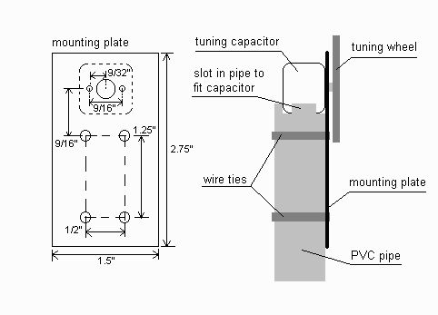
The measurements given in the drawing above are just guidelines. Actual dimensions and the sizes of the holes depend on the capacitor and the size of wire ties you intend to use. To prevent the mounting plate from sliding on the PVC pipe, cut or file a slot in the top of the PVC pipe into which the capacitor will have a snug fit. This will result in a secure mount for the tuning capacitor.
After mounting the tuning capacitor on the PVC pipe, you can go ahead and make the electrical connections. Solder the tabs of C1 through C4 together first. The tabs are probably long enough to do this. If not, use something like #14 wire, solder wick, or any other larger diameter wire. Make sure you do not connect any of the center tabs to this assembly. In the picture below you’ll see that I have one unused tab. The reason for this will be explained in the Testing and Tuning section.
Initially, all 4 capacitors have to be connected. Next take a short piece of large diameter wire and solder it to the assembly. The other end of this wire needs to be soldered to one side of the main loop. I have used the braid from a piece of RG-8 coax cable to make the connections to the main loop, but almost anything will do. Then take another piece of large diameter wire and solder one end to the center tab, and the other end to the other side of the main loop.
The main part of the SSTML is now finished. You can already test it by holding the whip antenna of your shortwave receiver very close to the upper half of the loop and tune the receiver to, say, 15 MHz. Rotate the tuning wheel clockwise until it doesn’t go any further. Then slowly rotate the tuning wheel counter clockwise. At some point you will notice an increase in the noise coming from your receiver, and perhaps you’ll even be able to hear the WWV station. There will definitely be a peak in the noise, and when you rotate the tuning wheel further, the noise will decrease again.
The next step is to build the coupling loop that will pick up the energy generated in the main loop and offer it to the receiver.
Coupling Loop
When you look at the many designs of magnetic loops on the internet, or in various other publications, you’ll notice that there are different ways to construct coupling loops. Some don’t even use a loop, but a gamma match to connect the magnetic loop to the feedline. However, this would require another variable capacitor. Other designs use a coupling loop built from coax cable, and the center conductor and braid have to be connected in a certain way to minimize noise pickup. I’ve experimented quite a bit with different types of coupling loops, including complex ones built from 4 pieces of coax, but I noticed no difference in performance compared to the simple wire loop. So let’s keep this simple.
I constructed the coupling loop from solid #14 house wire. The size of the wire is not critical at all; just pick a size of whatever you have laying around that will keep its shape once mounted on the PVC support pipe. The length of the wire should be about 2 feet if the circumference of the main loop is 10 feet. In other words the length of the wire for the coupling loop is one fifth of that of the main loop.
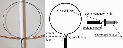
Bend the wire in the shape of a circle and solder one end to the center conductor of the feedline (coax) and the other end to the braid. Use some electrical tape or shrink tubing to cover the exposed parts. On the other end of the coax you can attach a connector that will fit into your receiver’s external antenna jack. One of my favorite receivers, a Radioshack DX-398, uses a 3.5 mm phone jack that is easily obtainable at Radioshack. Solder the center conductor to the tip of the plug and the braid to the sleeve. Check the manual of your receiver to find out what the correct plug is and how the coax needs to be connected.
Once the coupling loop is completed you can attach it to the PVC support pipe with a few wire ties. The coupling loop needs to be mounted on the opposite side of the tuning capacitor, which is the bottom of the main loop.
Feedline
The feedline of choice is coax for this antenna. This is mainly a choice of convenience, as you can route coax much more easily than balanced feedlines. Which type of coax, or the length, doesn’t matter. You can use RG-58, but if you have only TV coax (RG-59, RG-6) available, then that will work just fine. Use whatever you have.
Tripod
I built the tripod from 3 threaded rods, 9 nuts, and a short piece of one-inch schedule 40 PVC pipe. Drill three holes at the same angle through the PVC pipe, but at different heights. The rods have to overlap each other inside the pipe, so each successive hole has to be higher than the previous one (a little over 1 time the diameter of the rod).

The yellow rubber caps can be found in the hardware section of the hardware store, probably in the same area where they store the threaded rods. Before inserting the PVC support pipe of the SSTML you can drop a rubber ball into the tripod. Though not absolutely necessary, the ball will act as a ball bearing, and will help make rotating the loop a bit smoother.
Testing
Once you have completed the loop, it should look something like this:
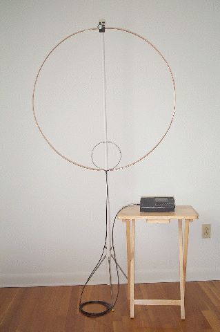
You can test the loop by connecting it to your receiver and trying to determine the upper and lower tuning limits.
First, make sure all trimmers on the tuning capacitor are open. Open means that the two halves (two half moon shaped pieces of metal) of the trimmer do not overlap. You can use a regular small screwdriver to do this.
To find the lower limit, connect a receiver to the loop and turn the tuning wheel/knob on the antenna fully counter clockwise. Turn the receiver on and tune it to 5 MHz. If you can select a step size on your receiver, select 5 kHz, and make sure the receiver is in the AM mode. In case the receiver has different filter settings, choose the widest filter available. Now tune the receiver up in frequency and listen to the noise level. At some point you will notice that the noise increases. Write down where you think the noise is at a maximum. On my loop that is around 5.3 MHz.
Now, to find the upper limit, tune the receiver to 25 MHz and turn the tuning wheel/knob on the loop fully clockwise. Tune the receiver down in frequency in 5 kHz steps and write down where you find the noise to be at a maximum. At 23.2 MHz I find the maximum noise on my loop.
You now know the tuning range of your loop. My loop tunes from the 49 meter band all the way up to the 13 meter broadcast band. This includes the 40, 30, 20,17 and 15 meter amateur radio bands. Your loop may have somewhat different values for the lower and upper limits depending on the range of your tuning capacitor.
Fine Tuning (optional)
The loop will probably cover all the shortwave bands you’re interested in without any fine tuning. However, if you find that the loop does not cover a band you want near the upper or lower tuning limit, it may be possible to add that band with some fine tuning. Keep in mind that if you raise the upper tuning limit, you will also raise the lower tuning limit and vice versa. Changing the tuning range of this loop antenna is like moving a sliding window over the shortwave bands.
If you’d like to raise the upper limit, you’ll have to lower the minimum value of the variable tuning capacitor. This can be done by disconnecting one of the four capacitors. The trick is, of course, to find which capacitor needs to be disconnected. This has to be done by trial and error if no test equipment is available.
The tuning capacitor used here has two large capacitors and two small ones. One of the smaller capacitors needs to be disconnected. Since you don’t know which one that is, simply disconnect one of the tabs of C1 through C4. Make sure the tuning wheel on the loop is rotated fully clockwise. Now tune the receiver to the previously found upper limit and then tune up in frequency. Note where you find the new maximum noise level. If you don’t find this point, tune the receiver to 29990 kHz (upper limit of the shortwave band) and rotate the tuning wheel on the loop counter clockwise. If you find that you have to tune back the loop quite a bit, like 1/8 to 1/4 of a turn, then you probably disconnected a large capacitor. Reconnect the capacitor you just disconnected. Disconnect a different one and repeat the procedure described in this paragraph. If you now find that the upper limit has been raised by just a few MHz, then you know you disconnected a small one. Hopefully you’ll now be able to tune the loop where you’d like it to tune. Remember though, that now the lower limit is raised also.
You can lower the lower limit somewhat by using the trimmers. First tune the receiver to the lower limit you found earlier. Now close one of the trimmers by rotating one of the screws 180 degrees with a screwdriver. This will add about 20pF (pico-Farad) to the total capacitor value. Not much, but it may be just enough. Since there are 4 trimmers, you can add 80pF in total. After you closed the first trimmer, tune the receiver down in frequency and find the new lower limit (tune for maximum noise). If that’s not enough, close another trimmer and find the new lower limit. If that’s still not enough, you can close the third and fourth trimmer. Hopefully that will bring the lower limit to where it needs to be. Keep in mind that the loop will probably not tune much lower than 5 MHz. Also remember that by lowering the lower limit you also lower the upper limit. This may mean that though you gain one band at the lower end, you may lose two or three bands at the upper end. You’ll have to decide which is most beneficial to you. Since we’re on the downward slope of the sunspot cycle, it may be more beneficial to lower the lower limit than raise the upper limit of the loop.
Of course you can try all kinds of combinations of closing trimmers and/or disconnecting capacitors. This will give you a wide variety of ranges, but can easily drive you crazy. Try to remember the sliding window principle. Adding capacity (i.e. closing the trimmers) will lower the lower and upper limits. Reducing capacity (i.e. disconnecting a capacitor) will raise the lower and upper limits.
Results
So how good is this loop, anyway? Compared to the built-in whip antenna, it may very well be the difference between copying a signal comfortably or not hearing it at all. Consider the following recording:
choose
Sample Recording (MP3
200kB)
or Sample Recording
(WAV 1.4Mb)
This is a 12 second recording of a part of a conversation (QSO) between amateur radio operators in the 20 meter band (14 MHz.). The receiver is a DX-398 portable. The loop was positioned right next to the receiver. For the first 4 seconds I used the loop antenna. Then I switched to the whip antenna for the next 5 seconds, and then switched back to the loop. As you can hear, the difference is dramatic. The signal is virtually inaudible on the whip, but very clear on the loop.
You can see an example of how well it can reduce noise from nearby noise sources on my random wire vs. magnetic loop page. I compared a random wire antenna strung throughout an apartment to a magnetic loop antenna. Even though the loop used in that example was built also for transmitting, the results are the same when it comes to receiving. By pointing the broadside of the loop at an offending noise source, like a TV or computer monitor, the noise can be effectively reduced.
You may notice that due to the pre-selecting properties of the magnetic loop your receiver will be less likely to overload, especially compared to a random wire antenna. This will greatly enhance the enjoyment of shortwave listening on a sensitive receiver.
Conclusion
It does take some time and effort to build this loop, but I’m confident you’ll be pleased with the results. This loop took me about an afternoon to built, not including the tripod. Sure, stringing up a random wire antenna is a whole lot easier and quicker, but the results can be far less than desirable, especially in a noisy apartment setting.
It may sound somewhat complicated to build this antenna, especially the tuning section, but it really isn’t. In fact you don’t have to go through the tuning procedure at all. Chances are that even without fine tuning the antenna already covers all the bands you’re interested in. It’s a fun antenna to build and it gives you a greater sense of accomplishment than just stringing up a random wire. You’re actually building an antenna.
I hope you’ll enjoy your loop as much as I enjoy mine. Don’t let the declining number of sunspots keep you from enjoying your favorite shortwave radio show.
If you have any questions or suggestions, please do not hesitate to drop me an email.
73,
--Alex, KR1ST